- Arduino Uno
- Arduino Seeeduino
- Triple axis accelerometer
- Triple axis rate gyroscope
- Triple axis magnetometer
- Pressure transducer
- Pitot-Static Probe
- Rx multiplexer (RxMUX)
- Radio Transmitter
- Radio Receiver
- 9v and 5v rechargeable batteries
The main reason that two Arduino boards were used for this project was because this project required more RAM that was available on a single board. We chose to use the Arduino boards because they were already purchased and the goal of this lab was to build an autopilot system with equipment that was already available in-house.
Two different power sources were used on board this aircraft. A lightweight lithium-polymer 9 volt battery was used to power both of the Arduino boards and the sensors. A 5 volt nickel-cadmium pack was used to power the servos, RxMux, and the radio receiver. A diagram of how everything is interconnected is shown in Figure 1.
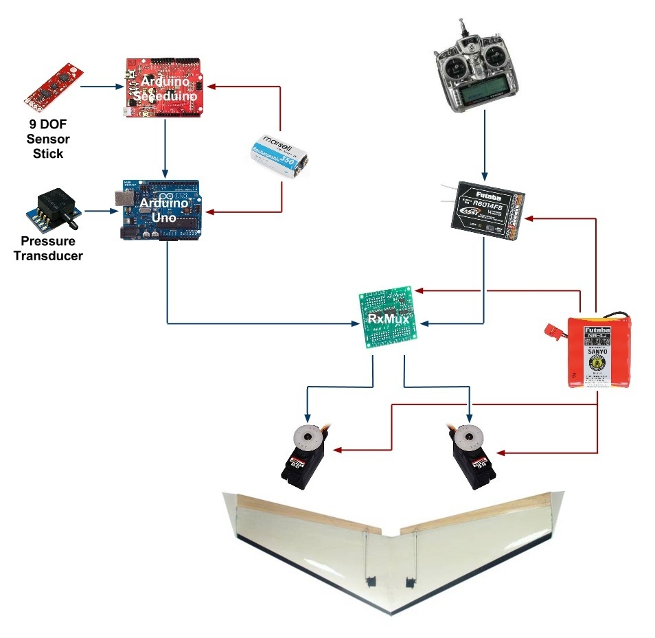
The RxMux (shown in Figure 1) allows the system to be switched from manual control to autonomous control using a switch located on the radio receiver. This allows a human pilot to stabilize the aircraft after launch before switching control to the autopilot system.
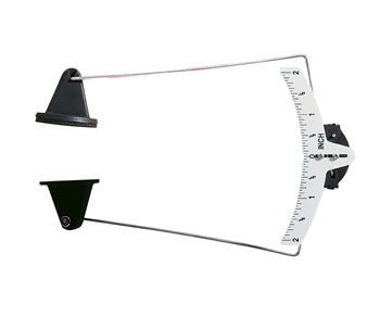
In addition to installing the hardware, calibrations were performed for the pressure transducer as well the control surfaces (ailevons). The pressure transducer (and pitot-static probe) were calibrated using the aero jet on the ground floor of Hammond Building. The control surface deflections were calibrated using the control surface deflection meter shown in Figure 2.
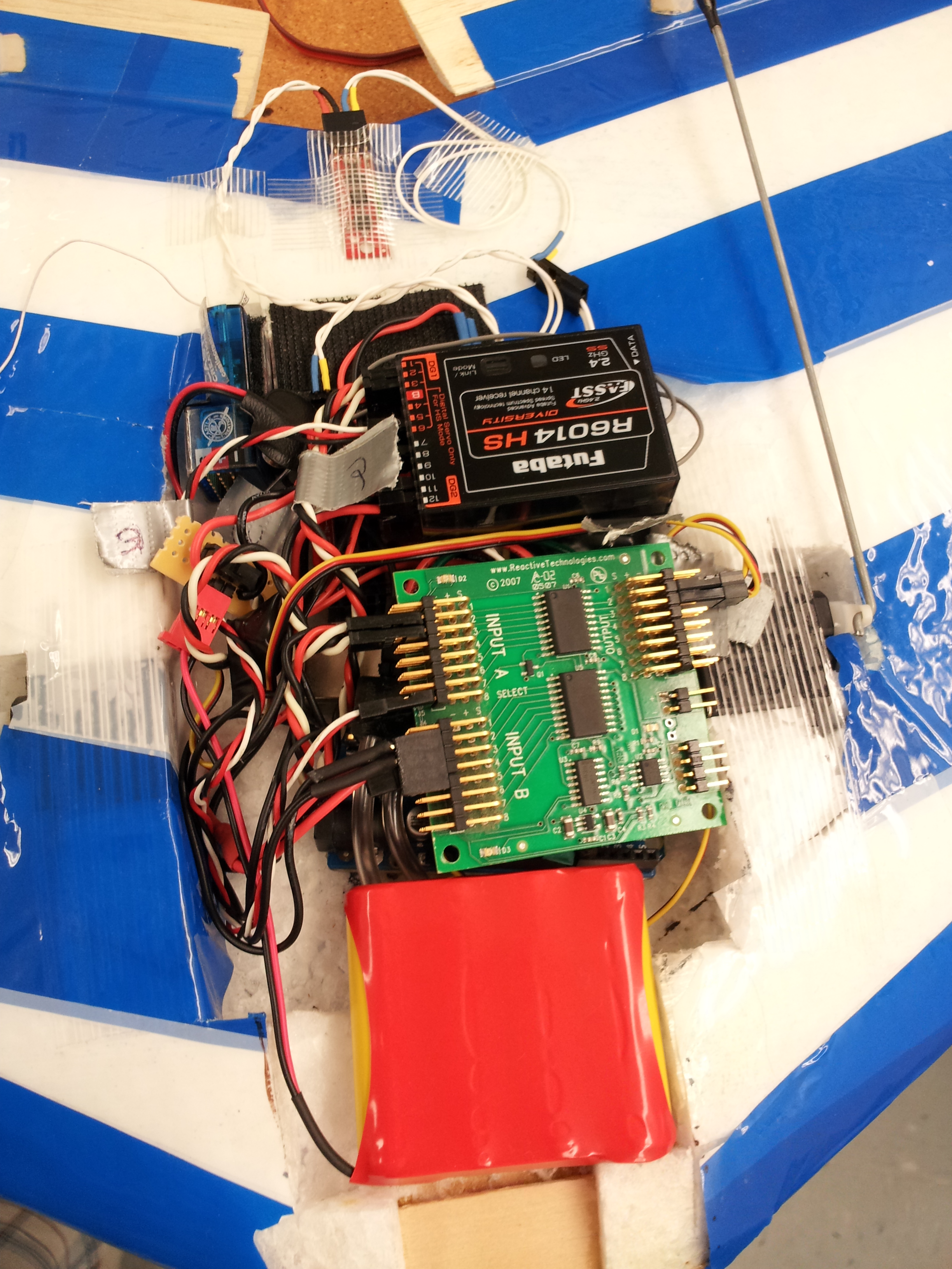
The hardware was placed in a rectangular section that was cut out of the chasis of the Zagi flying wing. The installed hardware is shown in Figure 3.