
Integrating rate gyroscopes provides an easy way to determine aircraft attitude, but small drifts in the gyroscope bias will quickly cause the attitude estimate to diverge. The typical method attitude filters use to correct the drift is to reference the gravity vector, measured with an accelerometer. With this inertial reference the aircraft attitude can be easily determined.
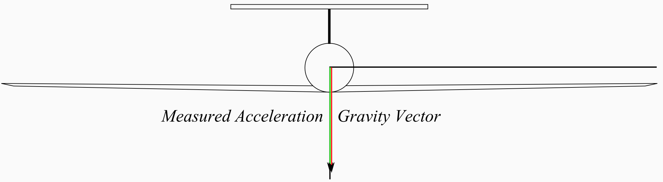
While this method works well for aircraft which predominately fly straight and level, during accelerated flight (such as turning), the estimate will drift from the correct attitude as the (body) z component of the acceleration increases without a corresponding increase in the other components. For short turns the drift is small and is corrected after turning. For a soaring aircraft which could spend long periods of time turning, the drift would reach unacceptable levels and prevent precise control of the aircraft.

To tailor the attitude estimator better for soaring flight, a filter is created that uses the magnetic field as an inertial reference. Because magnetometer readings are unaffected by accelerations during turns, attitude can be accurately estimated even during prolonged turns. Use of the magnetic field brings both benefits and challenges - the largely horizontal nature of the magnetic field allows the yaw angle to be determined, but also reduces the sensitivity in the roll and pitch axes. During testing this effect was seen in relatively large pitch and roll excursions that were occasionally needed in order to fully converge the attitude estimation. One of the goals of this project is to determine if the excursions typically seen in soaring flight are enough to provide good estimation of attitude on all axes.

The implementation of the attitude filter is accomplished using an Unscented Kalman Filter, providing an accurate estimation of the non-linear system describing the aircraft motion. The Unscented Kalman Filter models the state and covariance of the system by using the state estimate as well as a number of "sigma points" - points surrounding the estimate which define the shape of the state probability distribution. Modeling the probability distribution in this way gives a better estimate of the output than linearization.
The prediction step of the filter projects the aircraft attitude one step forward using the body rates measured by the gyroscopes and the current estimated attitude to describe the relationship between body and Euler rates. As a UKF is used, the sigma points are propagated forward along with the current estimated state.
The update step takes the estimated state and sigma points from the prediction and determines the readings that should be taken by the magnetometer. Comparing the measured to predicted readings allows the state estimate to be corrected to bring the estimated and measured field readings in line. As with the prediction step, sigma points are also propagated through the updates.
The filter implemented here is heavily based on a MATLAB/Simulink implementation of this filter that was created by Jack Langelaan and Nick Grande. It follows the general outline for the UKF described in [1].
The hardware realization of the attitude estimator presented some difficulty. Accurate estimation requires the use of arrays of floating-point numbers. Initial attempts to implement the filter on an ATmega 328 were hampered by the limited RAM available. The code was subsequently moved to an ATmega 1280, which had enough RAM to run the estimator. Even with the 1280, there is not enough spare memory or processing power to run the controller as well, so the estimator and controller are run on separate boards, with an i2c connection between.
The IMU sensors are located on a Sparkfun 9DoF board, with three axis gyro, magnetometer, and accelerometers. All sensors communicate with the ATmega 1280 using i2c. The sensor board is located close to the aircraft's center of gravity but well away from the servos to avoid interference with the magnetometer.
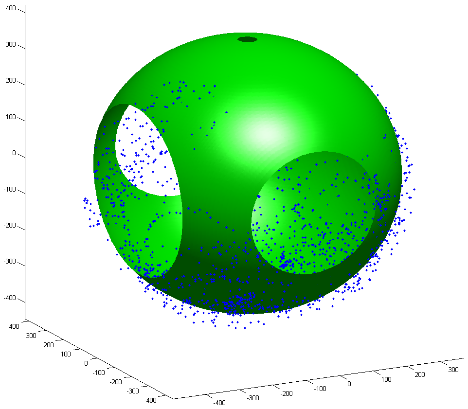
In order to ensure accurate readings, calibration of the magnetometer is required. Applying a known field to the magnetometer was not possible, so calibration is performed by rotating the magnetometer to point it in a number of directions then fitting an ellipsoid to the resulting data. The center of the ellipsoid gives the magnetometer offsets, and the relative lengths of the axes gives scaling factors. A local reference is also defined by taking measurements for a few minutes with the aircraft at "zero-zero-zero," then defining the mean of those measurements as the reference. This calibration method is sufficient since only the direction of the magnetic field is required, not the magnetic field itself, in fact measurements are scaled to unit length immediately after being taken.
The use of a locally defined and calibrated magnetic field, works for an aircraft flying in a small area, but would not work if the aircraft were to cover long distances due to changes in the magnetic field at different points on the earth, in which case a model for the earth's magnetic field would have to be employed.
References:
Thrun, S., Burgard, W., Fox, D., "Gaussian Filters," Probabilistic Robotics, 1st ed., MIT Press, Massachusetts, 2006.